Quick answer
In short
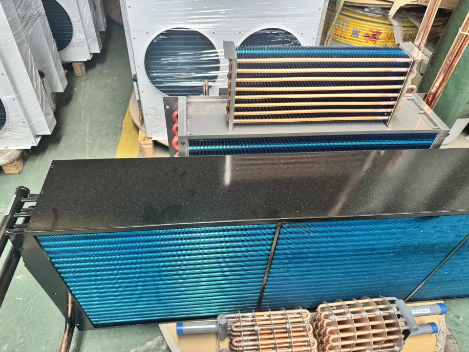
A replacement coil is a new coil built to fit the space and connections of an existing one. To quote it, the supplier needs the finned height and finned length, the number of tube rows and tubes high, the fins per inch, the tube outside diameter, the casing dimensions and flanges, and the size, type and position of each connection, with the connection side stated as seen in the direction of airflow. The nameplate, any original datasheet and the current operating conditions let the duty be checked. Uniinox reviews replacement-core requests from these measurements, photos and any available drawing.
Measure the finned area and the casing
Start with the coil itself, not the unit it sits in. The finned area sets the face area and tube length; the casing and flanges decide whether the new coil fits the same opening and fixings. The measurement list below follows the method published by Marlo Heat Transfer Solutions for ordering a replacement coil.
| Measurement | How to take it | Why it matters |
|---|---|---|
| Fin height (FH) | Height of the finned area, across the tubes | Sets the face area and the number of tubes high |
| Fin length (FL) | Length of the finned area, along the tubes | Sets the face area and the tube length |
| Casing length, height and depth | Overall casing dimensions, plus flange widths | The new coil must fit the same opening and fixings |
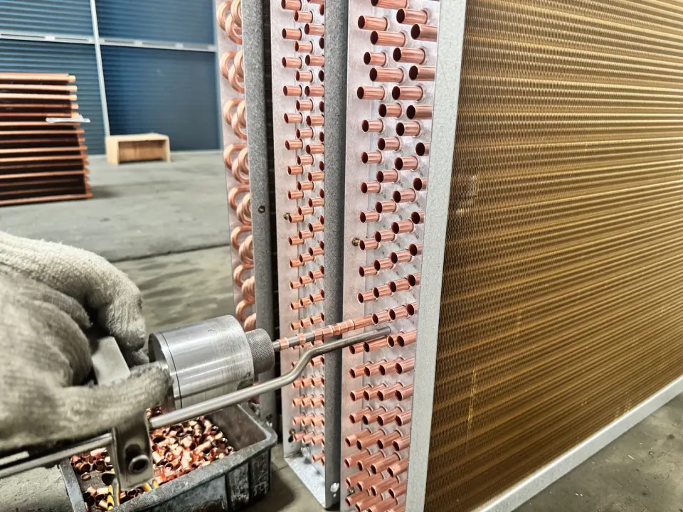
| Tube rows | Count the tubes across the coil depth, including any hidden by the headers | Rows set the surface area and the air pressure drop |
| Tubes high | Count the tubes from top to bottom | With the fin height, gives the tube spacing |
| Fins per inch | Count the fins over 3 or 4 inches and divide by that length | Changes capacity, pressure drop and cleaning |
| Tube outside diameter | Measure over the tube with a gauge or caliper | Sets the return bends and header design |
Record the connections and handing
For each connection, record the size, the type (male or female thread, flange or plain stub), the material and its position, measured from two casing edges to the centre of the stub. Note the number of tubes feeding each header, whether the tubes run horizontally or vertically, the airflow direction and whether the casing is pitched or straight.
Right-hand and left-hand coils are mirror images. Marlo determines the connection side by looking at the coil in the direction of airflow; whichever convention your drawing uses, mark the connection side on a photo so there is no doubt. Photograph the connection side with a tape measure in view.
Check the duty before copying the old coil
An exact copy is only right if the system still runs the way it did. If the airflow, fluid, glycol concentration or refrigerant has changed, or the old coil never met its duty, send the current operating conditions so that the replacement can be checked rather than copied. The nameplate and any original datasheet help identify the design.
A refrigerant change can also change the material: ammonia, for example, cannot be used with copper tubes.
Related: Heat exchanger RFQ checklist, Stainless steel vs copper coils
Materials, coating and the reason for replacement
If the coil is being replaced because of corrosion, leaks or fin damage, say so and send photos. The cause can change the specification: a coating, another fin material, a heavier tube wall or a different tube material. Uniinox's documented finned-core capability references cover tube outside diameters of 6 to 32 mm and fin thickness of 0.10 to 0.25 mm; other specifications are reviewed against the drawing.
What to send for a quotation
The list below is the minimum for a first technical review. Photos, sketches or a size list help if you do not have a complete drawing yet.
- Photos of both coil faces, the connection side and the nameplate
- Fin height, fin length and casing dimensions with flanges
- Tube rows, tubes high, fins per inch and tube outside diameter
- Connection size, type, material, position and the connection side
- Coil type: cooling, heating, DX evaporator or condenser, with the fluid or refrigerant
- Current operating conditions, the reason for replacement, coating and quantity
Frequently asked questions
Questions about this application
Can a coil be replaced using only the model number?
A model number can help identify the original design, but Uniinox builds to measured dimensions or a drawing. Send the measurements and photos as well, so the new coil can be checked against the space and connections.
How do I tell whether a coil is right-hand or left-hand?
One common method, used in Marlo's replacement guide, is to look at the coil in the direction of airflow and note which side the connections are on. Conventions differ between drawings, so mark the connection side on a photo of the coil.
How do I count fins per inch?
Count the fins over 3 or 4 inches and divide by that length. To convert to fin pitch in millimetres, divide 25.4 by the fins per inch.
Do I need the original coil's performance data?
It is strongly recommended. With the original datasheet or nameplate and the current operating conditions, the replacement can be checked against the duty instead of only matching the dimensions.
Primary sources
Technical references
These references support the general points above. They do not certify a Uniinox product or replace the approved project design.
- How to Measure a Coil to Order a Marlo ReplacementMarlo Heat Transfer Solutions
Lists the measurements used to specify a replacement coil: fin height and length, fins per inch, rows and tubes high, casing and flanges, connection positions, sizes, types and the connection side viewed in the direction of airflow.
- Cooling Coil and Drain Pan Requirements for Air Handling Units (DRM News to Use, August 2015)NIH Office of Research Facilities
Owner design requirement: cooling-coil face velocity not above 2.0 m/s (400 fpm) at present design, at most 8 rows and 10 fins per inch, stainless sloped drain pans extending at least 12 in downstream, and removable coils.
- Air-Cooling and Dehumidifying Coils, Chapter 23ASHRAE Handbook—HVAC Systems and Equipment, 2024
Selection factors for air-cooling coils, including duty, air conditions, coolant data, dimensions and pressure-drop limits.