Quick answer
In short
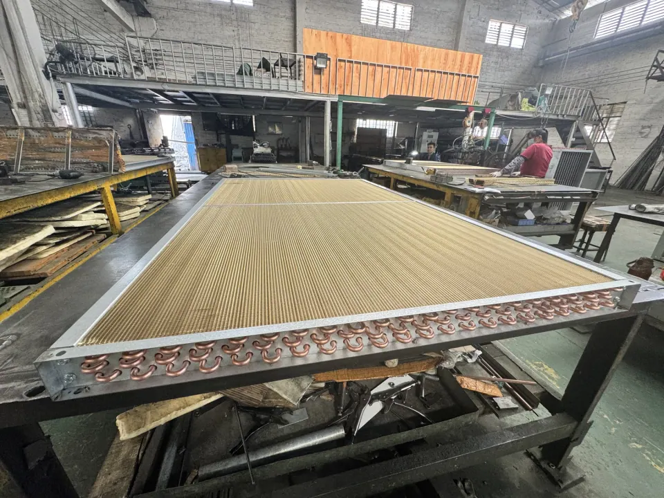
An air handling unit coil is a finned-tube heat exchanger installed in the unit's airstream. Chilled water or a glycol solution, hot water, or an evaporating refrigerant (a DX coil) flows through the tubes while air passes across the fins. The coil is defined by its finned length and height, rows deep, fin spacing, tube size, circuiting and connections, and it is selected from the airflow, the entering and leaving air conditions and the fluid temperatures and flow. Uniinox builds copper-tube finned cores to the project drawing; capacity and pressure drop are confirmed against the operating data for each project.
Key facts at a glance
Published owner standards show the kind of limits engineers specify. They are examples rather than universal rules: use the values in your own project specification.
| Topic | Example requirement | Source |
|---|---|---|
| Coil types | Water, glycol solution, steam and refrigerant coils | AHRI ACHC program |
| Cooling-coil face velocity | Not above 2.0 m/s (400 fpm) at present design conditions | NIH Design Requirements Manual |
| Rows and fins | At most 8 rows deep and 10 fins per inch | NIH Design Requirements Manual |
| Fin spacing | At least 0.125 in (3.2 mm) between fins | Michigan State University standard |
| Drain pan | Stainless, sloped to a bottom drain, at least 12 in downstream of the coil | NIH Design Requirements Manual |
| Certified ratings | Coils for central-station AHUs under non-frosting conditions | AHRI ACHC program |
Which coils an air handling unit uses
A cooling coil lowers the air temperature and, when its surface is below the dew point of the air, removes moisture that drains away as condensate. It is usually supplied with chilled water or a water and glycol solution. A heating coil raises the air temperature with hot water. A direct-expansion (DX) coil is the evaporator of a refrigeration circuit: refrigerant evaporates inside the tubes and cools the air directly.
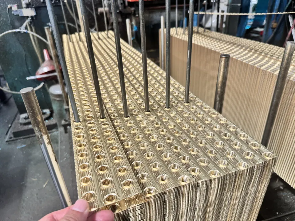
All three share the same basic construction: rows of tubes, closely spaced fins, return bends and headers with connections. The duty, fluid and air conditions decide the rows, fin spacing and circuiting, so two coils with the same face size can perform very differently.
Related: HVAC coils and finned tube heat exchanger cores, Industrial evaporator coils
Face velocity and moisture carryover
Face velocity is the airflow divided by the finned face area of the coil. On a cooling coil it decides whether condensate stays on the fins and drains, or is blown off the coil into the unit and ductwork. Many building owners therefore cap it in their design standards.
Two published examples: the NIH Design Requirements Manual sets a nominal cooling-coil face velocity of no more than 2.0 m/s (400 fpm) at present design conditions, with up to 2.5 m/s (480 fpm) allowed for future capacity. Michigan State University's construction standard limits chilled-water and refrigerant coils to 500 fpm across the finned area. A lower face velocity needs a larger face area for the same airflow, so state the limit that applies before the coil size is fixed.
| Published limit | Applies to | Source |
|---|---|---|
| 2.0 m/s (400 fpm) | Cooling coils at present design conditions | NIH Design Requirements Manual |
| 2.5 m/s (480 fpm) | Cooling coils sized with future growth capacity | NIH Design Requirements Manual |
| 500 fpm (about 2.5 m/s) | Chilled-water and refrigerant coils, finned area | Michigan State University standard |
Rows, fin spacing and cleaning access
Deeper coils and denser fins add surface but are harder to clean. The NIH requirements limit cooling coils to 8 rows deep and 10 fins per inch, and the MSU standard asks for fin spacing of at least 0.125 in (3.2 mm), which is about 8 fins per inch. Fin spacing is usually quoted in fins per inch (FPI); the fin pitch in millimetres is 25.4 divided by the FPI.
If the coil will be cleaned in place, state the cleaning method and the maximum rows and fin density your maintenance team accepts. NIH also requires access doors for inspection and maintenance, and coils that can be removed without major rigging.
| Fins per inch | Fin pitch |
|---|---|
| 6 FPI | 4.2 mm |
| 8 FPI | 3.2 mm |
| 10 FPI | 2.5 mm |
| 12 FPI | 2.1 mm |
| 14 FPI | 1.8 mm |
Condensate drain pans and stacked coils
Cooling coils need a drain pan that empties completely. NIH specifies a stainless steel pan with a positive slope to a bottom drain, extending at least 12 in downstream of the cooling coil, and a separate intermediate pan for the upper coils in a stacked bank. The MSU standard also requires an intermediate pan for stacked coils.
State whether the drain pan, casing and frame are part of the coil supply or are provided by the unit manufacturer. A coil core quoted on its own does not include them.
Freeze protection for water coils
A water coil that sees entering air below 0 °C can freeze and split its tubes. Common protections are a glycol solution in the loop or a procedure for draining the coil when it is out of service. Glycol lowers capacity and changes the pressure drop, so the type and concentration must be known when the coil is sized. The MSU standard also asks for removable headers to be omitted on glycol coils.
What to send for a quotation
The list below is the minimum for a first technical review. Photos, sketches or a size list help if you do not have a complete drawing yet.
- Coil service: cooling, heating, preheat or DX (refrigerant)
- Airflow and entering and leaving air dry-bulb and wet-bulb or relative humidity
- Fluid: water or glycol type and percentage, entering and leaving temperatures and flow; for DX, the refrigerant and evaporating temperature
- Finned length and height, rows, fin spacing and tube outside diameter, or the space available
- Maximum face velocity and allowable air-side and fluid-side pressure drop
- Connection side, size and type, casing and drain-pan scope, coating, testing and quantity
Frequently asked questions
Questions about this application
What face velocity should an AHU cooling coil be designed for?
There is no single value. Many owner standards cap it to limit moisture carryover: NIH requires no more than 2.0 m/s (400 fpm) at present design conditions, and Michigan State University specifies a maximum of 500 fpm across the finned area for chilled-water and DX coils. Use the value in your project specification and include it in the RFQ.
How many fins per inch does an HVAC coil have?
It depends on the duty and the cleaning requirement. Some owners set limits: NIH allows at most 10 fins per inch on cooling coils, and MSU requires at least 0.125 in between fins, about 8 fins per inch. Fin pitch in millimetres is 25.4 divided by the fins per inch.
Can Uniinox build a replacement coil for an existing air handling unit?
Uniinox reviews replacement-core requests from the existing coil's measurements, drawing or datasheet. Send the finned dimensions, rows, fin spacing, tube size and connection details, together with the operating conditions so the duty can be checked rather than only copied.
Is an AHU coil the same as a complete air handling unit?
No. The coil is one component. Fans, filters, dampers, casing, controls and drain pan are separate items unless the RFQ lists them as part of the supply.
Primary sources
Technical references
These references support the general points above. They do not certify a Uniinox product or replace the approved project design.
- Cooling Coil and Drain Pan Requirements for Air Handling Units (DRM News to Use, August 2015)NIH Office of Research Facilities
Owner design requirement: cooling-coil face velocity not above 2.0 m/s (400 fpm) at present design, at most 8 rows and 10 fins per inch, stainless sloped drain pans extending at least 12 in downstream, and removable coils.
- Section 238216 Air Coils, Construction StandardsMichigan State University Infrastructure Planning and Facilities
Owner specification: chilled-water and refrigerant coils limited to 500 fpm finned-area face velocity, fin spacing of at least 0.125 in, intermediate drain pans for stacked coils and no removable headers on glycol coils.
- Forced-Circulation Air-Cooling and Air-Heating Coils (ACHC) certification programAir-Conditioning, Heating, and Refrigeration Institute
Covers coils for field installation in built-up systems, duct-mounted coils and central-station air-handling units under non-frosting conditions.
- Air-Cooling and Dehumidifying Coils, Chapter 23ASHRAE Handbook—HVAC Systems and Equipment, 2024
Selection factors for air-cooling coils, including duty, air conditions, coolant data, dimensions and pressure-drop limits.