Product family / 07
Industrial condensers
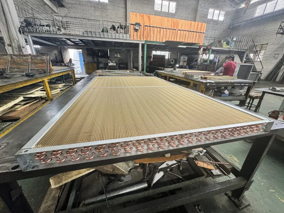
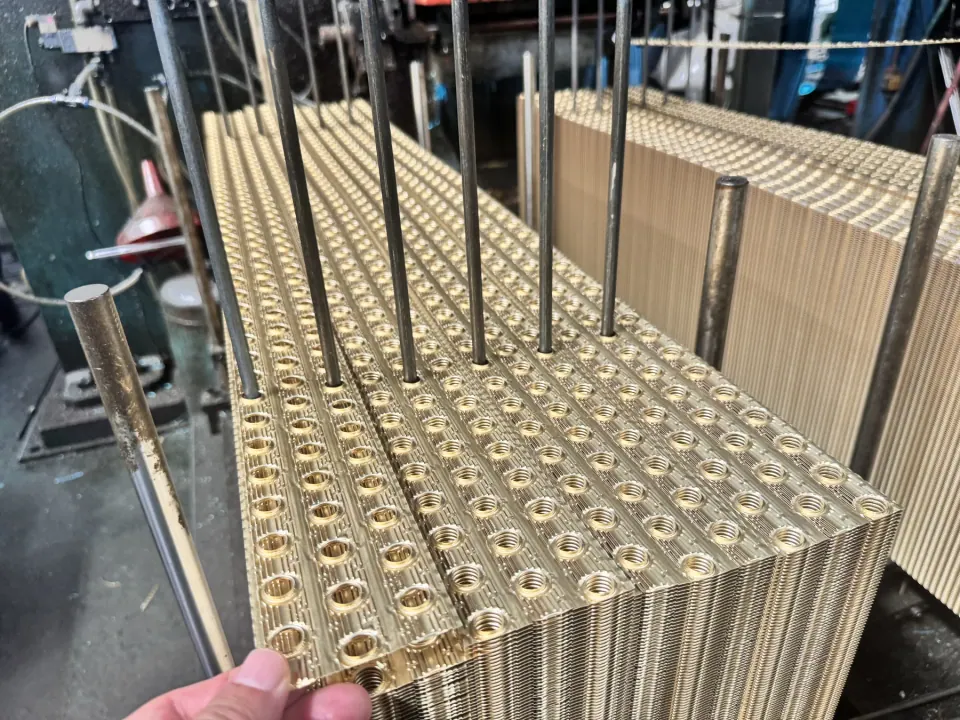
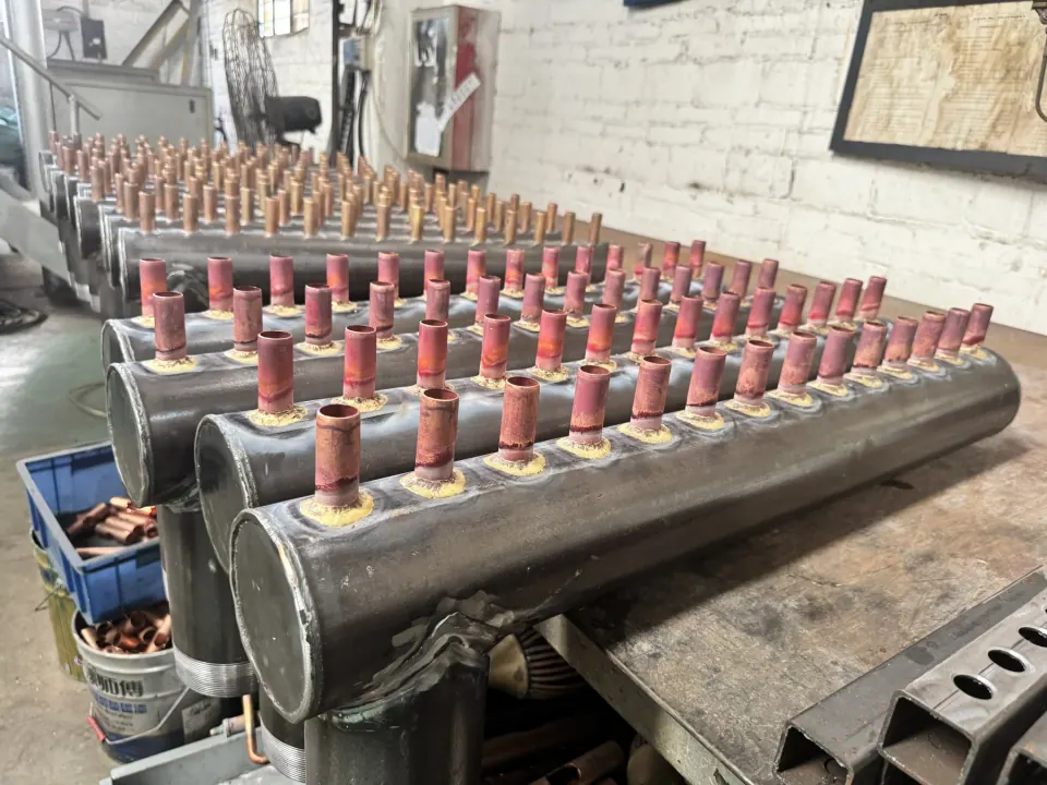
Uniinox coordinates fin preparation, copper tube insertion, return bends, headers and final assembly for custom condenser projects. Capacity and performance are not assigned from a photograph: each quotation starts with duty, refrigerant, airflow, temperatures, allowable pressure drop and the installation envelope.
Quick answer
How should this product be specified?
An industrial condenser rejects heat from a refrigerant or process medium to air, water or another cooling medium. A project-specific review needs the heat-rejection duty, working fluids, condensing and cooling-side conditions, airflow or flow rate, allowable pressure drops, installation envelope, connections and supply boundary.
Documented scope
A clear starting point, with final details controlled by the drawing.
- Compact and large-format finned core construction
- Copper tube, fin pack, return bend and header coordination
- Airflow and refrigerant data reviewed for each project
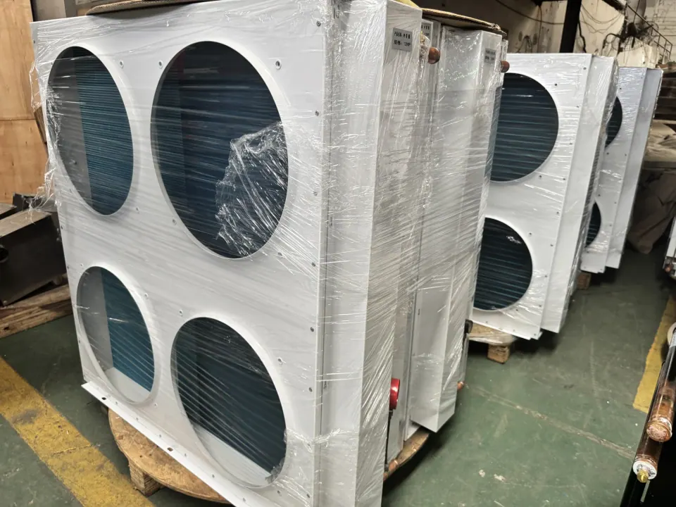
Evidence source: Finned core manufacturing stages and finished assemblies shown in supplied factory photography.
Selection and project scope
Prepare a condenser enquiry with a defined operating point
State the intended condenser service, refrigerant or process medium, required duty and the temperatures used for selection. Include airflow, available face area, maximum depth and connection locations. If you are replacing an existing core, provide its drawing and operating information as well as photographs.
Make clear whether the enquiry covers a bare finned core, headers and frame, or a larger assembly. Specify the requested inspection scope and documentation before quotation. The condenser-versus-evaporator guide helps organise the service information; the air cooler and OEM pages cover requests with additional equipment interfaces.
View the heat exchangers catalogSelection checklist
Industrial condenser selection inputs
Record the actual project operating point and supply boundary. These inputs support a technical review; they are not a published rating for every condenser configuration.
| Input | What to provide | Why it matters |
|---|---|---|
| Heat-rejection duty | Required capacity plus normal and maximum operating points | Defines the heat the condenser must reject at the stated conditions |
| Refrigerant or process medium | Fluid identity, condensing condition, flow information and circuit constraints | Establishes the hot-side basis and connection review |
| Cooling side | Airflow or cooling-medium flow, inlet condition, ambient range and target outlet condition | Defines where the rejected heat must go |
| Pressure-drop limits | Allowable pressure drop for each controlled side, with units | Prevents capacity from being considered without its flow penalty |
| Installation and connections | Maximum envelope, airflow direction, mounting points, access and connection orientation | Confirms fit and service access in the intended equipment |
| Supply boundary | Core, headers, frame, casing, fans, controls, coating, testing, quantity and documents | Separates the heat exchanger from surrounding equipment and project responsibilities |
Buyer questions
Before you request a quotation
What should I send when requesting an industrial condenser?
Identify the working fluid and cooling medium, required duty, operating temperatures and pressures, available space and connection details. For replacement work, attach the existing datasheet and installation drawing.
Can a condenser be selected from its photo or overall size?
A photo or envelope dimension cannot establish capacity. The selection needs the stated operating conditions and heat-transfer requirements; the quotation should identify the conditions used for review.
RFQ checklist
Include these inputs for a useful review.
- 01Refrigerant or working medium and required heat-rejection duty
- 02Entering and leaving temperatures, airflow and ambient condition
- 03Available envelope, fin spacing, tube rows and connection layout
- 04Allowable pressure drop, coating, testing and quantity