Product family / 04
Integrated assemblies
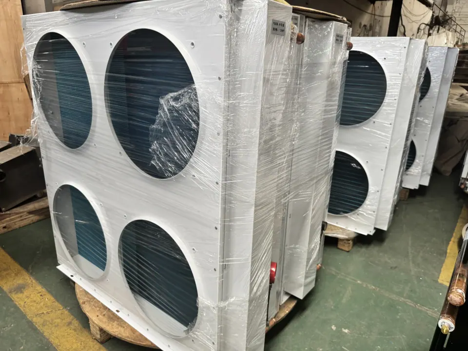
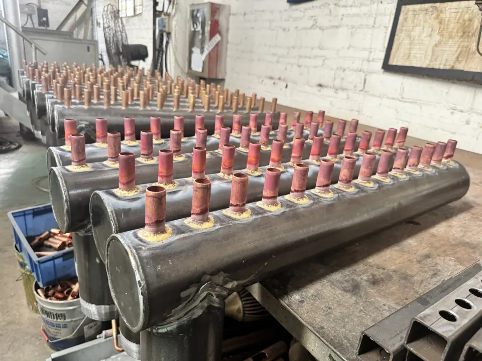
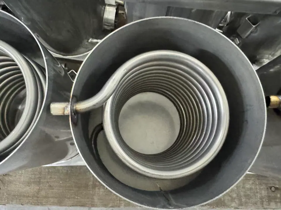
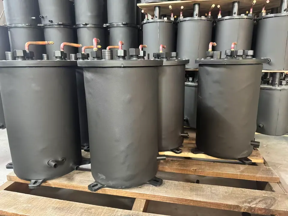
The supplied photography shows internal vessel coils, multi-connection headers and packaged air-cooled units. Final product naming, capacity, flow direction and electrical data must follow the approved drawing and nameplate.
Quick answer
How should this product be specified?
This route is for a coil or heat-exchanger core supplied together with its vessel or header interfaces. Send the coil drawing and a separate interface drawing showing access, supports, ports and included components. If the enquiry covers the complete equipment bill of materials and finished-unit release, use the custom OEM assembly route instead.
Documented scope
A clear starting point, with final details controlled by the drawing.
- Coil, header, frame and casing coordination
- Connection layout confirmed before assembly
- Finished-unit and shipment preparation support
Evidence source: Assembly and finished-product references supplied in factory photography.
Selection and project scope
Define the subassembly boundary at the vessel or header
Use this route when the requested deliverable is a defined heat-transfer subassembly: for example, an internal vessel coil with its support or connection arrangement, or a coil and header set with controlled port locations. A photograph can identify the general arrangement; the vessel opening, installed clearance and mating connection dimensions must come from the project drawings.
Mark each supplied and customer-supplied component on an interface list. Include the coil or core, headers, supports, mounting plate, frame and connection fittings only where they belong to the requested supply. This prevents a component set from being mistaken for a complete tank or air-cooled unit.
For repeat orders, provide the assembly reference, drawing revisions and the inspection records expected with each shipment. Use the custom OEM assembly route when a complete bill of materials, casing or finished-unit release is required; use the air cooler route for airflow, fan and enclosure interfaces. No capacity or electrical scope can be inferred from the example photographs.
View the heat exchangers catalogSelection checklist
Tank and header interface checklist
Define the interfaces for the subassembly being purchased; mark complete-equipment requirements separately.
| Input | What to provide | Why it matters |
|---|---|---|
| Installation access | Vessel opening, internal clearance, insertion and removal path | Checks whether the assembled coil or module can reach its intended position |
| Coil or core | Controlled drawing, material, tube size, geometry and service conditions | Identifies the actual heat-transfer component rather than assuming a pictured configuration |
| Header and ports | Port count, size, orientation and mating dimensions | Aligns the supplied connections with customer equipment |
| Support boundary | Mounting plate, supports, frame and customer-supplied parts | Separates the supplied subassembly from the surrounding vessel or unit |
| Release records | Drawing revisions, agreed inspection, identification, packing and quantity | Keeps repeat deliveries tied to the approved scope |
Buyer questions
Before you request a quotation
How should I define a heat-transfer assembly for quotation?
List each required component and its interface: coil or core, shell, supports, ports and mounting points. Identify which components are included in the supply and which will be provided by your installation team.
Does an assembly photo confirm that controls and testing are included?
No. Photos document a physical configuration, not the contractual supply or test scope. Specify controls, inspection records and acceptance requirements separately in the inquiry.
RFQ checklist
Include these inputs for a useful review.
- 01Assembly drawing, interface points and installation constraints
- 02Fluid circuit, connection direction and service conditions
- 03Casing, coating, frame and electrical requirements where applicable
- 04Inspection, packing, nameplate and delivery requirements